- 主营产品:
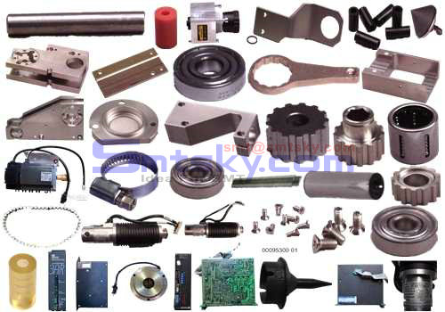
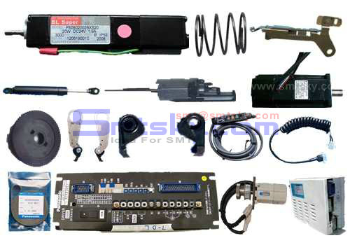
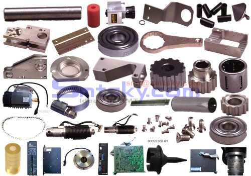
- 主营产品: SMT/AI OEM配件;SMT/AI原装件:如FEEDER NOZZLE MOTOR DRIVER CONTROL-BOARD SENSOR CYLINDER VALVE CUTTER等;PCB线路板锡膏印刷机配件:网板清洁卷纸,刮刀架/刀片,PCB夹边等;SMT接料胶片;防静电产品;电动工具;仪表仪器;SMT周边设备;SMT焊料:FUJI红胶/锡膏;SMT设备保养用油;SMT清洁用品:无尘纸/无尘布/工业擦试纸;波峰焊/回流焊配件等;更多信息请登录:www.smtsky.com.
- 所在地区:
- 广东 珠海 --
- 联系电话:
- 0756-3899556
- 手机号码:
- 联 系 人:
- 公司邮箱:
- smt@smtsky.com
- 总人气:2647
- 商铺人气:1241
- 产品人气:1395
- 资讯人气:11
产品展示列表
格力LED工业照明灯 省钱才是硬道理优点:1、光源好 灯珠寿命超过50000小时,寿命亦可达5.7年以上2、用电省 碳化硅灯珠,光衰更小,功耗更低3、防护佳 IP65防护等级,防止粉尘和雨水4、散热快 高效全铝散热器,高低翅片优化设计5、设计美 铝拉丝合金面板 钢化玻璃面罩 晶莹剔透6、电源优 交流176-265V 直流140-400V 满足太阳能供电或直流微网客户特殊要求
编号
名称
规格
NOZZLE211
NOZZLE212
NOZZLE213
NOZZLE214
NOZZLE215
5322 214 91038
TC PIP-CONTROL BOARD
1 PCS-SPARE 29/7/10
9965 000 14992
TC- PIGGY BOARD
9498 396 01387
TAPE COVER 8MM
9498396 02439
CONTROL BOX 8 MM
Email:smt@smtsky.com,Website:www.smtsky.com
Email:smt@smtsky.com,Website:www.smtsky.com
Email:smt@smtsky.com,Website:www.smtsky.com
4022 594 10050
FEEDER MOTOR KS 9INDEX) 8MM
5322 361 11113
TOP FOIL PEEL-OFF MOTOR
9498 396 00194
CABLE ASSY
5322 402 11168
HANDLE ASSEMBLY
9965 000 14444
CONTACK PIN ( 5PCS)
4022 516 12300
SPROCKET WHEEL(5 pcs )
9498 396 02047
PEAL OF PLATE ( use for component hight ststic)
9498 396 00974
PEAL OF PLATE ( our side ude this )
9498 396 01389
CLAMPING UNIT 8-24
532246683072
CENTERING BLOCK
Email:smt@smtsky.com,Website:www.smtsky.com
Email:smt@smtsky.com,Website:www.smtsky.com
Email:smt@smtsky.com,Website:www.smtsky.com
5322 4796 0108
NOZZLE 1005 (PA2747/00)
5322 214 91038
TRANSPORT CONTROLLER ( PIGGY PIP BOARD)
9965 000 14992
TRANSPORT CONTROLLER ( PIGGY SMALL BOARD)
9498 397 00308
HEAD ASSEMBLY UNIT ( LAS -RECORDITIONED SET)
9498 387 00004
PPU REPAIR
5322 218 11853
PPU RECORND
5322 281 20176
P VALVE (COMPRESS AIR VALVE)
5322 360 10365
E VALVE (AIR CHANEL VALVE )
5322 281 20173
V VALVE(VACCUM VALVE )
5322 214 9133
PIP CONTROL BOARD REPAIR
Email:smt@smtsky.com,Website:www.smtsky.com
Email:smt@smtsky.com,Website:www.smtsky.com
Email:smt@smtsky.com,Website:www.smtsky.com
5322 358 31302
BELTING-Y MOTOR
RAIL KAIZEN MR.INAMURA
5322 214 91177
VALM BOARD PIP
5322 214 91176
DRIVER BOARD TC-PPU
CONNECTOR 16-P
LAS CABLE LONG TYPE( 4 CABLE)
CABLE 16 P (1,5M)
LAS CABLE LONG TYPE( 4 CABLE)
884W011
LASER CABLE & TIUBING
884W012
LASER CABLE SHOOT
PPU CABLE ( 2 CABLE )
PPU CABLE CONNECTOR ( 2 CABLE )
Email:smt@smtsky.com,Website:www.smtsky.com
Email:smt@smtsky.com,Website:www.smtsky.com
Email:smt@smtsky.com,Website:www.smtsky.com
5322 479 30166
CORBON BRUSH ( 2 PCS )
A005 N610052027AA ... MOTOR 1 (MSMD042PJA) S
N006 N510010689AA ........ COUPLING 1 SFC-035SA2-9B-14B
N007 N510004723AA ... NUT 1 FU00SS
N008 N510003427AA ....... BEARING 1 7000ADBC8P5
N009 XLC6201ZZ ........... BALL BEARING 1 6201ZZ
N010 N510034921AA ..... WASHER 1 87FWSSB-D16.0-V5.0-T2.
N011 N310P921S1 ... SENSOR 1 P921S1
N012 N310P921SA1 ... SENSOR 2 PANADAC921SA1
N022 N510032158AA .... WASHER 1 87FWSSB-D15.0-V10.0-T3
N024 N510037864AA ....... BALL SCREW 1 GZ1510ES-ZAPR-0744X069
Email:smt@smtsky.com,Website:www.smtsky.com
Email:smt@smtsky.com,Website:www.smtsky.com
M40
X-Y.-...部(Y軸駆動部)
X-Y TABLE SECT.(Y-AXIS DRIVING SECT.)
X-Y.-...部(Y軸駆動部)
X-Y TABLE SECT.(Y-AXIS DRIVING SECT.)
.... No. REF No. PART No. 品 番 部 PART NAME 品 名 Q'TY 個数 REMARKS 備 考 R 1 R 2
002 N210084043AB ......(...) BRACKET(MOTOR) 1
004 X01L21011 ....... HOUSING 1
006 N210068163AA .... HOLDER 1
007 N210027736AA ....... BEARING 1
Email:smt@smtsky.com,Website:www.smtsky.com
Email:smt@smtsky.com,Website:www.smtsky.com
008 X00K02068 ...... STOPPER 4
009 X00K02069 ... COLLAR 4
012 1087104015 .....(Y ) PLATE(Y) 3
019 N210084055AB .... COVER 1
A013 N610052028AA ... MOTOR 1 (MSMD082PJA) S
N011 N310P921S1 ... SENSOR 1 P921S1
N012 N310P921SA1 ... SENSOR 2 PANADAC921SA1
N014 N510010690AA ........ COUPLING 1 SFC-040SA2-13B-19B
N015 KXF0234AA00 ...... LOCK-NUT 1 FU02SC
N016 N510034922AA ..... WASHER 1 87FWSSB-D20.0-V15.0-T5
Email:smt@smtsky.com,Website:www.smtsky.com
Email:smt@smtsky.com,Website:www.smtsky.com
N017 N510003493AA ....... BEARING 1 7202ADBP5
N018 XLC6202ZZ ........... BALL BEARING 1 6202ZZ
N019 N510033408AA ..... WASHER 1 87FWSSB-D20.0-V5.0-T3.
N020 N510030839AA .... SWITCH 1 LS-11S/RL S
N021 KXF0DG3AA00 ..... CABLE 1 V-M20
N023 N510037865AA ....... BALL SCREW 1 GZ2010ES-ZAPR-0588X050
N501 XPJ6A10FW ....... PARALLEL PIN 5 6X10,m6A,STEEL
M42
X-Y.-...部(.....部1)
X-Y TABLE SECT.(TABLE SECT.-1)
Email:smt@smtsky.com,Website:www.smtsky.com
Email:smt@smtsky.com,Website:www.smtsky.com
X-Y.-...部(.....部1)
X-Y TABLE SECT.(TABLE SECT.-1)
.... No. REF No. PART No. 品 番 部 PART NAME 品 名 Q'TY 個数 REMARKS 備 考 R 1 R 2
015 X01L21081 ..... PLATE 1
016 1087104020 ...... BRACKET 1
017 1087104021 ...... BRACKET 1
020 N210084054AA .... COVER 2
022 X01L21106 .... COVER 1
025 N210081970AA Y ..... Y-TABLE 1
027 1087104016 ....... DOG FOR SENSOR 1
Email:smt@smtsky.com,Website:www.smtsky.com
Email:smt@smtsky.com,Website:www.smtsky.com
N001 N513SSR2-A44 ............ (Y) LINEAR MOTION UNIT(Y) 2 SSR20XW2UUC1+1130LH-2
N002 N513C5 ..... CAP 38 C5
N003 N513SSR1-810 ............ (X) LINEAR MOTION UNIT(X) 2 SSR15XW2UUC1+1180LHY-2
N004 N513C4 ..... CAP 40 C4
N020 N510030839AA .... SWITCH 1 LS-11S/RL S
N021 KXF0DG3AA00 ..... CABLE 1 V-M20
N501 XPJ6A10FW ....... PARALLEL PIN 4 6X10,m6A,STEEL
M44
X-Y.-...部(.....部2)
X-Y TABLE SECT.(TABLE SECT.-2)
Email:smt@smtsky.com,Website:www.smtsky.com
Email:smt@smtsky.com,Website:www.smtsky.com
X-Y.-...部(.....部2)
X-Y TABLE SECT.(TABLE SECT.-2)
.... No. REF No. PART No. 品 番 部 PART NAME 品 名 Q'TY 個数 REMARKS 備 考 R 1 R 2
013 108710401701 ...... (L) BRACKET(L) 1
014 1087104018 ...... (R) BRACKET(R) 1
023 N210084127AA ...... BRACKET 1
A024 N610056204AB X ..... X-TABLE 1
N025 N510036735AA ...... JOINT 1 L80106021-301
N026 N510036737AA ......... GREASE NIPPLE 2 L50003000-001
N027 N510036736AA ...... JOINT 1 L80206021-301
Email:smt@smtsky.com,Website:www.smtsky.com
Email:smt@smtsky.com,Website:www.smtsky.com
N028 N510036733AA ...... JOINT 1 1823391784
N029 N510036734AA ...... JOINT 1 1823391008
N501 XPJ6A10FW ....... PARALLEL PIN 3 6X10,m6A,STEEL
N502 N434SH0W-048 ..... TUBE 1 NYLON4
M46
X-Y.....部(配線配管部)
X-Y TABLE SECT.(WIRING & PIPING SECT.)
X-Y.....部(配線配管部)
X-Y TABLE SECT.(WIRING & PIPING SECT.)
.... No. REF No. PART No. 品 番 部 PART NAME 品 名 Q'TY 個数 REMARKS 備 考 R 1 R 2
Email:smt@smtsky.com,Website:www.smtsky.com
Email:smt@smtsky.com,Website:www.smtsky.com
N610055729AA ............. WIRING & PIPING UNIT 1
001 N210069670AB ..... GUIDE 1
002 N210069671AB ..... GUIDE 1
003 N210069673AA ... NUT 7
004 N210069675AB ...... BRACKET 2
005 N210069676AB ...... BRACKET 3
006 N210069677AB ...... BRACKET 1
007 N210069678AB ...... BRACKET 3
008 N210087140AA ...... BRACKET 1
009 N210069680AA ..... PLATE 1
Email:smt@smtsky.com,Website:www.smtsky.com
Email:smt@smtsky.com,Website:www.smtsky.com
010 N210069681AA ..... PLATE 1
011 N210069682AB ..... PLATE 1
012 N210087144AA ..... PLATE 1
013 N210087360AA ...... BRACKET 1
014 N210069848AA .......... CONNECTOR BRACKET 1
015 N210069849AD .......... CONNECTOR BRACKET 1
016 104130415601 ...... BRACKET 3
017 1041304153 ..... PLATE 1
N001 N986HMWT-056 ......... ADHESIVE TAPE 1 HMW-TAP-WER No.2
N002 N510018158AA ...... FLUSH HEAD SCREW 34 M3X6-4.8 A2J (Trivalen
Email:smt@smtsky.com,Website:www.smtsky.com
Email:smt@smtsky.com,Website:www.smtsky.com
N003 N510018249AA ....... TRUSS HEAD SCREW 8 M3X4-4.8 A2J (Trivalen
N004 N986HMWT-M67 .... TAPE 1 HMW-TAP-WAR No.11/4
N005 N348EL10 ..... BUSHING FOR WIRING 1 EL-10
M48
...........部(共通部)
LOADER & UNLOADER SECT.(COMMOM SECT.)
...........部(共通部)
LOADER & UNLOADER SECT.(COMMOM SECT.)
.... No. REF No. PART No. 品 番 部 PART NAME 品 名 Q'TY 個数 REMARKS 備 考 R 1 R 2
N610061299AA .............. LOADER & UNLOADER UNIT 1
Email:smt@smtsky.com,Website:www.smtsky.com
Email:smt@smtsky.com,Website:www.smtsky.com
008 1099705118 ..... PULLEY 1
009 109970512002 .... LEVER 2
010 N210066358AB ..... PLATE 1
011 N210066359AB ... RAIL 1
016 N210066363AA ... PIN 2
018 N210066362AB ... HOSE 1
020 N210066364AA ...... BRACKET 2
A002 N610067724AA .... FRAME 1
N002 XLC6001ZZ ........... BALL BEARING 2 6001ZZ
N007 M0PC3917 ........... CAP FOR CAPACITOR 1 MOPC3917
Email:smt@smtsky.com,Website:www.smtsky.com
Email:smt@smtsky.com,Website:www.smtsky.com
N008 N510031513AA ........ GEAR HEAD 1 M4GA12.5F
N009 KXF0DY6MA00 ..... BUSHING 4 80F-0805
N011 N310P919T .... SWITCH 2 P919T
N012 N510024734AA ..... WASHER 2 87WSF16
N014 N5541AP34N O.... O-RING 1 1AP34N
N022 N648MB019000 ..... (.....) PULLEY(TENSION) 2 MB019000
N024 KXF04D1AA00 C ........... RETAINING RING C-TYPE,SHAFT 4 STW-8
N025 XPJ5A12FW ....... PARALLEL PIN 2 5X12,m6A,STEEL
N030 XYN4+J8FN ................ PAN HEAD M/C SCREW & W. 4 M4X8, STEEL, P.C
N031 N510043758AA .... LEVER 1 LUDM-52-5X25-BK
Email:smt@smtsky.com,Website:www.smtsky.com
Email:smt@smtsky.com,Website:www.smtsky.com
N501 N510018282AA ....... TRUSS HEAD SCREW 12 M4X8-4.8 A2J (Trivalen
N502 N510017332AA .... BOLT 2 M3X50-10.9 A2J (Trival
N504 N510017849AA ....... HEXAGON NUT 2 M3-6H-4T A2J (Trivalen
N505 N510017419AA ............ HEX. SOCKET HEAD CAP BOLT 2 M5X8-10.9 A2J (Trivale
N506 N510017354AA ............ HEX. SOCKET HEAD CAP BOLT 8 M4X20-10.9 A2J (Trival
N507 N510017428AA ............ HEX. SOCKET HEAD CAP BOLT 4 M6X12-10.9 A2J (Trival
N509 N510017398AA ............ HEX. SOCKET HEAD CAP BOLT 3 M5X20-10.9 A2J (Trival
N510 N510017855AA ....... HEXAGON NUT 2 M4-6H-4T A2J (Trivalen
N511 N510017475AA ............ HEX. SOCKET HEAD CAP BOLT 2 M8X30-10.9 A2J (Trival
N512 N510018438AA ............. HEX. SOCKET SET SCREW 9 M4X6-45H A2J (Trivalen
Email:smt@smtsky.com,Website:www.smtsky.com
Email:smt@smtsky.com,Website:www.smtsky.com
N513 N510018497AA ............. ROUND PLAIN WASHER 14 4 10H A2J (Trivalent)
N514 N510018499AA ............. ROUND PLAIN WASHER 3 5 10H A2J (Trivalent)
N516 N510017341AA ............ HEX. SOCKET HEAD CAP BOLT 4 M3X8-10.9 A2J (Trivale
N517 N510017344AA ............ HEX. SOCKET HEAD CAP BOLT 4 M4X10-10.9 A2J (Trival
N518 N510018494AA ............. ROUND PLAIN WASHER 6 3 10H A2J (Trivalent)
N519 N510018327AA ........ SPRING WASHER 4 No.2 3 S A2J (Trivalen
V 1 308380500702 ... MOTOR 1 M4RA1G4L S
M50
...........部(共通部)
LOADER & UNLOADER SECT.(COMMOM SECT.)
Email:smt@smtsky.com,Website:www.smtsky.com
Email:smt@smtsky.com,Website:www.smtsky.com
...........部(共通部)
LOADER & UNLOADER SECT.(COMMOM SECT.)
.... No. REF No. PART No. 品 番 部 PART NAME 品 名 Q'TY 個数 REMARKS 備 考 R 1 R 2
001 N210066374AA ...... BRACKET 1
006 1099705110 ..... PLATE 2
007 N210066361AD .....(.... ) PLATE(BASE) 1
008 1099705118 ..... PULLEY 1
012 N210066360AB ... RAIL 1
013 109970513402 .... LEVER 2
014 109970513502 .... LEVER 1
Email:smt@smtsky.com,Website:www.smtsky.com
Email:smt@smtsky.com,Website:www.smtsky.com
015 N210066365AA .......... BALL SPLINE 1
016 N210066363AA ... PIN 2
017 N210066366AB .... SHAFT 1
019 1099705141 ..... SPACER 2
A001 N610067723AA .... FRAME 1
N001 N510027184AA .... BOLT 1 87UST8-30
N002 XLC6001ZZ ........... BALL BEARING 2 6001ZZ
N003 KXF023CAA00 ... NUT 2 FU07SS
N004 N510003302AA ........... BALL BEARING 4
N007 M0PC3917 ........... CAP FOR CAPACITOR 1 MOPC3917
Email:smt@smtsky.com,Website:www.smtsky.com
Email:smt@smtsky.com,Website:www.smtsky.com
N008 N510031513AA ........ GEAR HEAD 1 M4GA12.5F
N009 KXF0DY6MA00 ..... BUSHING 4 80F-0805
N010 N510036964AA ..... CYLINDER 1 CDBM2E32-50-DCL4298L
N012 N510024734AA ..... WASHER 2 87WSF16
N014 N5541AP34N O .... O-RING 1 1AP34N
N022 N648MB019000 .....(.....) PULLEY(TENSION) 2 MB019000
N024 KXF04D1AA00 C ........... RETAINING RING C-TYPE,SHAFT 4 STW-8
N025 XPJ5A12FW ....... PARALLEL PIN 2 5X12,m6A,STEEL
N029 N510013514AA ..... TERMINAL 1 N510013514AA S
N030 XYN4+J8FN ................ PAN HEAD M/C SCREW & W. 4 M4X8, STEEL, P.C
Email:smt@smtsky.com,Website:www.smtsky.com
Email:smt@smtsky.com,Website:www.smtsky.com
N032 N510038115AA ..... ORIFICE 2 R4.0X0.9
N501 N510018282AA ....... TRUSS HEAD SCREW 12 M4X8-4.8 A2J (Trivalen
N502 N510017332AA .... BOLT 2 M3X50-10.9 A2J (Trival
N503 N510017877AA ....... HEXAGON NUT 1 M8-6H-4T A2J (Trivalen
N504 N510017849AA ....... HEXAGON NUT 2 M3-6H-4T A2J (Trivalen
N505 N510017419AA ............ HEX. SOCKET HEAD CAP BOLT 2 M5X8-10.9 A2J (Trivale
N507 N510017428AA ............ HEX. SOCKET HEAD CAP BOLT 6 M6X12-10.9 A2J (Trival
N508 N510018501AA ............. ROUND PLAIN WASHER 5 6 10H A2J (Trivalent)
N509 N510017398AA ............ HEX. SOCKET HEAD CAP BOLT 3 M5X20-10.9 A2J (Trival
N510 N510017855AA ....... HEXAGON NUT 2 M4-6H-4T A2J (Trivalen
Email:smt@smtsky.com,Website:www.smtsky.com
Email:smt@smtsky.com,Website:www.smtsky.com
N511 N510017475AA ............ HEX. SOCKET HEAD CAP BOLT 2 M8X30-10.9 A2J (Trival
N512 N510018438AA ............. HEX. SOCKET SET SCREW 9 M4X6-45H A2J (Trivalen
N513 N510018497AA ............. ROUND PLAIN WASHER 4 4 10H A2J (Trivalent)
N514 N510018499AA ............. ROUND PLAIN WASHER 3 5 10H A2J (Trivalent)
N515 N510017435AA ............ HEX. SOCKET HEAD CAP BOLT 3 M6X20-10.9 A2J (Trival
N517 N510017344AA ............ HEX. SOCKET HEAD CAP BOLT 2 M4X10-10.9 A2J (Trival
N518 N510018494AA ............. ROUND PLAIN WASHER 2 3 10H A2J (Trivalent)
V 2 308380500602 ... MOTOR 1 M4RA1G4L S
V 5 N401DC73 ... SENSOR 2 D-C73
M52
Email:smt@smtsky.com,Website:www.smtsky.com
Email:smt@smtsky.com,Website:www.smtsky.com
...........部(共通部)
LOADER & UNLOADER SECT.(COMMOM SECT.)
...........部(共通部)
LOADER & UNLOADER SECT.(COMMOM SECT.)
.... No. REF No. PART No. 品 番 部 PART NAME 品 名 Q'TY 個数 REMARKS 備 考 R 1 R 2
008 1099705118 ..... PULLEY 1
009 109970512002 .... LEVER 2
010 N210066358AB ..... PLATE 1
012 N210066360AB ... RAIL 1
016 N210066363AA ... PIN 2
Email:smt@smtsky.com,Website:www.smtsky.com
Email:smt@smtsky.com,Website:www.smtsky.com
018 N210066362AB ... HOSE 1
020 N210066364AA ...... BRACKET 1
A001 N610067723AA .... FRAME 1
N002 XLC6001ZZ ........... BALL BEARING 2 6001ZZ
N007 M0PC3917 ........... CAP FOR CAPACITOR 1 MOPC3917
N008 N510031513AA ........ GEAR HEAD 1 M4GA12.5F
N009 KXF0DY6MA00 ..... BUSHING 4 80F-0805
N011 N310P919T .... SWITCH 1 P919T
N012 N510024734AA ..... WASHER 2 87WSF16
N014 N5541AP34N O .... O-RING 1 1AP34N
Email:smt@smtsky.com,Website:www.smtsky.com
Email:smt@smtsky.com,Website:www.smtsky.com
N022 N648MB019000 .....(.....) PULLEY(TENSION) 2 MB019000
N024 KXF04D1AA00 C ........... RETAINING RING C-TYPE,SHAFT 4 STW-8
N025 XPJ5A12FW ....... PARALLEL PIN 2 5X12,m6A,STEEL
N030 XYN4+J8FN ................ PAN HEAD M/C SCREW & W. 4 M4X8, STEEL, P.C
N031 N510043758AA .... LEVER 1 LUDM-52-5X25-BK
N501 N510018282AA ....... TRUSS HEAD SCREW 12 M4X8-4.8 A2J (Trivalen
N502 N510017332AA .... BOLT 2 M3X50-10.9 A2J (Trival
N504 N510017849AA ....... HEXAGON NUT 2 M3-6H-4T A2J (Trivalen
N505 N510017419AA ............ HEX. SOCKET HEAD CAP BOLT 2 M5X8-10.9 A2J (Trivale
N506 N510017354AA ............ HEX. SOCKET HEAD CAP BOLT 8 M4X20-10.9 A2J (Trival
Email:smt@smtsky.com,Website:www.smtsky.com
Email:smt@smtsky.com,Website:www.smtsky.com
N507 N510017428AA ............ HEX. SOCKET HEAD CAP BOLT 4 M6X12-10.9 A2J (Trival
N509 N510017398AA ............ HEX. SOCKET HEAD CAP BOLT 3 M5X20-10.9 A2J (Trival
N510 N510017855AA ....... HEXAGON NUT 2 M4-6H-4T A2J (Trivalen
N511 N510017475AA ............ HEX. SOCKET HEAD CAP BOLT 2 M8X30-10.9 A2J (Trival
N512 N510018438AA ............. HEX. SOCKET SET SCREW 9 M4X6-45H A2J (Trivalen
N513 N510018497AA ............. ROUND PLAIN WASHER 12 4 10H A2J (Trivalent)
N514 N510018499AA ............. ROUND PLAIN WASHER 3 5 10H A2J (Trivalent)
N516 N510017341AA ............ HEX. SOCKET HEAD CAP BOLT 2 M3X8-10.9 A2J (Trivale
N517 N510017344AA ............ HEX. SOCKET HEAD CAP BOLT 2 M4X10-10.9 A2J (Trival
N518 N510018494AA ............. ROUND PLAIN WASHER 6 3 10H A2J (Trivalent)
Email:smt@smtsky.com,Website:www.smtsky.com
Email:smt@smtsky.com,Website:www.smtsky.com
N519 N510018327AA ........ SPRING WASHER 4 No.2 3 S A2J (Trivalen
V 3 308380520702 ... MOTOR 1 M4RA1G4L S
M54
...........部(共通部)
LOADER & UNLOADER SECT.(COMMOM SECT.)
...........部(共通部)
LOADER & UNLOADER SECT.(COMMOM SECT.)
.... No. REF No. PART No. 品 番 部 PART NAME 品 名 Q'TY 個数 REMARKS 備 考 R 1 R 2
001 N210066374AA ...... BRACKET 1
006 1099705110 ..... PLATE 2
Email:smt@smtsky.com,Website:www.smtsky.com
Email:smt@smtsky.com,Website:www.smtsky.com
007 N210066361AD .....(.... ) PLATE(BASE) 1
008 1099705118 ..... PULLEY 1
011 N210066359AB ... RAIL 1
013 109970513402 .... LEVER 2
014 109970513502 .... LEVER 1
015 N210066365AA .......... BALL SPLINE 1
016 N210066363AA ... PIN 2
017 N210066366AB .... SHAFT 1
019 1099705141 ..... SPACER 2
A002 N610067724AA .... FRAME 1
Email:smt@smtsky.com,Website:www.smtsky.com
Email:smt@smtsky.com,Website:www.smtsky.com
N001 N510027184AA .... BOLT 1 87UST8-30
N002 XLC6001ZZ ........... BALL BEARING 2 6001ZZ
N003 KXF023CAA00 ... NUT 2 FU07SS
N004 N510003302AA ........... BALL BEARING 4
N007 M0PC3917 ........... CAP FOR CAPACITOR 1 MOPC3917
N008 N510031513AA ........ GEAR HEAD 1 M4GA12.5F
N009 KXF0DY6MA00 ..... BUSHING 4 80F-0805
N010 N510036964AA ..... CYLINDER 1 CDBM2E32-50-DCL4298L
N012 N510024734AA ..... WASHER 2 87WSF16
N014 N5541AP34N O .... O-RING 1 1AP34N
Email:smt@smtsky.com,Website:www.smtsky.com
Email:smt@smtsky.com,Website:www.smtsky.com
N022 N648MB019000 .....(.....) PULLEY(TENSION) 2 MB019000
N024 KXF04D1AA00 C ........... RETAINING RING C-TYPE,SHAFT 4 STW-8
N025 XPJ5A12FW ....... PARALLEL PIN 2 5X12,m6A,STEEL
N029 N510013514AA ..... TERMINAL 1 N510013514AA S
N030 XYN4+J8FN ................ PAN HEAD M/C SCREW & W. 4 M4X8, STEEL, P.C
N032 N510038115AA ..... ORIFICE 2 R4.0X0.9
N501 N510018282AA ....... TRUSS HEAD SCREW 12 M4X8-4.8 A2J (Trivalen
N502 N510017332AA .... BOLT 2 M3X50-10.9 A2J (Trival
N503 N510017877AA ....... HEXAGON NUT 1 M8-6H-4T A2J (Trivalen
N504 N510017849AA ....... HEXAGON NUT 2 M3-6H-4T A2J (Trivalen
Email:smt@smtsky.com,Website:www.smtsky.com
Email:smt@smtsky.com,Website:www.smtsky.com
N505 N510017419AA ............ HEX. SOCKET HEAD CAP BOLT 2 M5X8-10.9 A2J (Trivale
N507 N510017428AA ............ HEX. SOCKET HEAD CAP BOLT 6 M6X12-10.9 A2J (Trival
N508 N510018501AA ............. ROUND PLAIN WASHER 5 6 10H A2J (Trivalent)
N509 N510017398AA ............ HEX. SOCKET HEAD CAP BOLT 3 M5X20-10.9 A2J (Trival
N510 N510017855AA ....... HEXAGON NUT 2 M4-6H-4T A2J (Trivalen
N511 N510017475AA ............ HEX. SOCKET HEAD CAP BOLT 2 M8X30-10.9 A2J (Trival
N512 N510018438AA ............. HEX. SOCKET SET SCREW 9 M4X6-45H A2J (Trivalen
N513 N510018497AA ............. ROUND PLAIN WASHER 4 4 10H A2J (Trivalent)
N514 N510018499AA ............. ROUND PLAIN WASHER 3 5 10H A2J (Trivalent)
N515 N510017435AA ............ HEX. SOCKET HEAD CAP BOLT 3 M6X20-10.9 A2J (Trival
Email:smt@smtsky.com,Website:www.smtsky.com
Email:smt@smtsky.com,Website:www.smtsky.com
N517 N510017344AA ............ HEX. SOCKET HEAD CAP BOLT 2 M4X10-10.9 A2J (Trival
N518 N510018494AA ............. ROUND PLAIN WASHER 2 3 10H A2J (Trivalent)
V 4 308380520602 ... MOTOR 1 M4RA1G4L S
V 5 N401DC73 ... SENSOR 2 D-C73
M56
...........部(.......連動部)
LOADER & UNLOADER SECT.(LOADER ARM SWING SECT.)
...........部(.......連動部)
LOADER & UNLOADER SECT.(LOADER ARM SWING SECT.)
.... No. REF No. PART No. 品 番 部 PART NAME 品 名 Q'TY 個数 REMARKS 備 考 R 1 R 2
Email:smt@smtsky.com,Website:www.smtsky.com
Email:smt@smtsky.com,Website:www.smtsky.com
N610066187AB ................ LOADER ARM SWING UNIT 1
001 108711600103 .... LEVER 1
002 N210066287AA ... PIN 1
003 N210066288AA .... LEVER 1
004 108711600402 ...... BRACKET 1
005 108711600502 ...... BRACKET 1
006 N210066306AC .... LEVER 1
007 N210082121AA .. CAM 1
008 108711600801 ...... BRACKET 1
009 1087116009 ... SPRING 1
Email:smt@smtsky.com,Website:www.smtsky.com
Email:smt@smtsky.com,Website:www.smtsky.com
N001 KXF0DYPHA00 ....... BEARING 1 F688AZZ1
N002 KXF0E2FJA00 ....... BEARING 1 688AZZ1
N003 KXF0DYM0A00 ............ SHOCK-ABSORBER 1 RBQ1604
N004 N533N0S4T ........ ROD END 2 N0S4T
N005 N533N0S4TL ........ ROD END 2 NOS4TL
N006 N510023244AA .... ROD 1 87LBMFN4-206
N007 N510023243AA .... ROD 1 87LBMFN4-184
N008 N510018253AA ....... TRUSS HEAD SCREW 2 M3X6-4.8 A2J (Trivalen
N009 N510034923AA ... PIN 1 87FXBB8-12-F9-MA4
N010 N531CF6RA ...... CAM FOLLOWER 1 CF6R-A
Email:smt@smtsky.com,Website:www.smtsky.com
Email:smt@smtsky.com,Website:www.smtsky.com
N011 N510022573AA ..... BUSHING 1 K5B1410
N012 N510034926AA .. SHIM 1 RB012016005
N013 N510034924AA .. SHIM 1 RB020024005
N014 N510033408AA ..... WASHER 1 87FWSSB-D20.0-V5.0-T3.
N015 KXF0E3LAA00 ....... BEARING 2 6802ZZ
M58
...........部(切欠き基板対応部)
LOADER & UNLOADER SECT.(P.C.B. CUTTING TYPE SECT.)
...........部(切欠き基板対応部)
LOADER & UNLOADER SECT.(P.C.B. CUTTING TYPE SECT.)
Email:smt@smtsky.com,Website:www.smtsky.com
Email:smt@smtsky.com,Website:www.smtsky.com
Detail G
Bridge Beam Assy
3
Tooling Plate
Rotary Table
Page 7
Dual Head Board Handling System L/R T46365906 Rev. D
This Document Supports Assembly 46365906 Rev. C
Email:smt@smtsky.com,Website:www.smtsky.com
Page 8
T46365906 Rev. D Dual Head Board Handling System L/R
DET
NO.
ITEM NO. DESCRIPTION QTY U/M
1 26465000 PLUNGER, SPRING 1 EA
2 40516601 BUSHING 1 EA
3 40516701 BRACKET 1 EA
4 45001001 PLATE, BEC MTG. 2 EA
6 46182602 BRKT, AUTO MISS MARKER 1 EA
Email:smt@smtsky.com,Website:www.smtsky.com
8 46217104 R. BRIDGE ASSY (L-R) 1 EA
9 46217204 L. BRIDGE ASSY (L-R) 1 EA
14 46248301 BAD BD LIFT ASSY 1 EA
16 46268402 AUTO MISS MARKER ASSY 2 EA
17 46275101 BLOCK, SHAFT SUPPORT 4 EA
18 46275301 SHAFT 2 EA
19 46277602 BAD BD HOPPER ASSY 1 EA
24 46312801 BRACKET, HOPPER MTG 2 EA
25 46366401 PLATE, WASHER 2 EA
26 46388801 WASHER 8 EA
Email:smt@smtsky.com,Website:www.smtsky.com
27 46411401 NUT, TEE 1 EA
28 46476102 TRANSFER ASSY 1 EA
29 46477101 BRACKET 1 EA
30 46477201 BRACKET 2 EA
33 80000403 SHCS 8-32 X 1/2 1 EA
34 80000515 SHCS 10-32 X 1/2 10 EA
35 80000516 SHCS 10-32 X 5/8 8 EA
36 80000604 SHCS 1/4-20 X 5/8 6 EA
37 80000607 SHCS 1/4-20 X 1 2 EA
38 80000608 SHCS 1/4-20 X 1 1/4 4 EA
Email:smt@smtsky.com,Website:www.smtsky.com
40 80000715 SHCS 5/16-18 X 3 1/4 8 EA
41 80002502 SFHS 8-32 X 1/2 4 EA
43 80011003 SHSS 1/4 X 5/8 1 EA
44 80013802 SPRG PIN .062 X .250 1 EA
45 80013807 SPRG PIN .062 X .562 2 EA
This Document Supports Assembly 46365906 Rev. C
Page 9
Dual Head Board Handling System L/R T46365906 Rev. D
46 80015003 HEX NUT 5/16-18 8 EA
Email:smt@smtsky.com,Website:www.smtsky.com
48 80018704 SLW #8 1 EA
49 80018705 SLW #10 18 EA
50 80018706 SLW 1/4 8 EA
51 80018707 SLW 5/16 16 EA
53 80018805 FW #10 14 EA
54 80018807 FW 1/4 4 EA
55 80018812 FW 3/8 16 EA
56 80023508 HEX NUT-MS 10-32 7 EA
58 BLKM07122 WASHER, SPRING 1 EA
USED BUT NOT SHOWN ITEMS
Email:smt@smtsky.com,Website:www.smtsky.com
59 46303606 DHVCD BH ELECT.ASSY L TO R 1 EA
60 46366006 L-R DHVCD PNEU ROUTING ASSY 1 EA
61 50546801 DOC, DH BHS MACH 46365905-08 1 EA
62 T46365906 DOC, L/R DHBH SYSTEM 1 EA
This Document Supports Assembly 46365906 Rev. C
Page 10
T46365906 Rev. D Dual Head Board Handling System L/R
Functional Description
The Board Handling System receives two boards from an input mechanism.
Email:smt@smtsky.com,Website:www.smtsky.com
The boards are then lowered and transferred to the positioning system of the
insertion machine for population. The populated boards are then raised and
transferred to an output mechanism.
The Board Handling System can interface with a wide variety of input/output
mechanism and can handle a full range of board widths.
Maintenance Concept
The customer is required to perform periodic maintenance. Included procedures
are cleaning, lubricating and checking for correct function. Customer
performed adjustments and corrective maintenance procedures are identified
in the following table. Adjustment or corrective maintenance procedures not
Email:smt@smtsky.com,Website:www.smtsky.com
identified in this document and those procedures in the advanced support information
paragraphs are to be performed by Universal Instruments field engineering
personnel only.
Maintenance Procedures
Recommended
Frequency
Minimum Skill
Required
Spares Kit
Required
Email:smt@smtsky.com,Website:www.smtsky.com
Clean/Lubricate Bridge Slides Quarterly
Maintenance
Technician
No
Clean/Adjust Belts Quarterly
Maintenance
Technician
Yes
Clean Board Support Inserts Annually
Maintenance
Email:smt@smtsky.com,Website:www.smtsky.com
Technician
No
Lubricate Idler Pulley Shafts Quarterly
Maintenance
Technician
No
Lubricate Board Locator Flanged
Bearings
Quarterly
Maintenance
Email:smt@smtsky.com,Website:www.smtsky.com
Technician
No
Lubricate Actuator Contact Surfaces Quarterly
Maintenance
Technician
No
Lubricate Board Pusher Quarterly
Maintenance
Technician
No
Email:smt@smtsky.com,Website:www.smtsky.com
Clean Rodless Cylinder Quarterly
Maintenance
Technician
No
Clean/Lubricate Bad Board Lift Slide
Shafts
Quarterly
Maintenance
Technician
No
Email:smt@smtsky.com,Website:www.smtsky.com
Lubricate Board Stop Shoulder Screws Quarterly
Maintenance
Technician
No
Lubricate Auto Miss-Mark
Slide/Housing
Quarterly
Maintenance
Technician
No
Email:smt@smtsky.com,Website:www.smtsky.com
This Document Supports Assembly 46365906 Rev. C
Page 11
Dual Head Board Handling System L/R T46365906 Rev. D
This Document Supports Assembly 46365906 Rev. C
Procedures and Adjustments
Adjustments and corrective maintenance procedures required of the customer
are presented in the following subsections.
Belt Replacement and Adjustment
When periodic maintenance indicates that the belts need to be replaced, perform
Email:smt@smtsky.com,Website:www.smtsky.com
the following procedure for all belt replacement. Refer to the beam assembly
illustrations for belt routing.
1. Power the insertion machine down.
2. Loosen the screws that secure the right angle drive motor into the motor
block.
3. Raise the right angle drive motor to release the tension on the belt and
slide the belt off the drive sprocket.
4. Slide the belt off the convex pulleys, drive pulley and idler pulleys.
5. Install the new belt onto the convex pulleys, drive pulley and idler pulleys
as shown.
Email:smt@smtsky.com,Website:www.smtsky.com
6. Raise the right angle drive motor and slide the belt onto the drive
sprocket.
7. Allow the weight of the right angle drive motor apply tension on the
belt. Mark the position of the right angle drive motor relative to the
motor block.
8. Lower the right angle drive motor .125 inch from the mark made in
step 7 to increase the belt tension and secure it in position by tightening
the screw against the motor block.
Do not over tighten the drive belts. Excessive tension will put too much
pressure on the pulleys and drive mechanism causing premature failure.
Email:smt@smtsky.com,Website:www.smtsky.com
When properly adjusted, the drive belts will transfer a five pound board
without slipping.
End of procedure.
Page 12
T46365906 Rev. D Dual Head Board Handling System L/R
This Document Supports Assembly 46365906 Rev. C
Motor Block
Right Angle
Drive Motor
Email:smt@smtsky.com,Website:www.smtsky.com
Output Beam Assemblies
Input Beam Assemblies
Page 13
Dual Head Board Handling System L/R T46365906 Rev. D
This Document Supports Assembly 46365906 Rev. C
Belt Speed Adjustment Procedure
Purpose
The board handling distribution board must be adjusted to provide correct
belt speed for board transfer.
Email:smt@smtsky.com,Website:www.smtsky.com
Special Tools
VOM (meter)
This procedure must be performed with the machine power on. Care
must be exercised to prevent personal injury due to contact with
exposed electrical circuits.
Wear a wrist strap connected to ground to prevent electrostatic
discharge from causing damage to PCBs.
Procedure:
1. Power on the machine as described in the Operation documentation.
2. Push the INTERLOCK push button.
Email:smt@smtsky.com,Website:www.smtsky.com
3. Turn the INTERLOCK BYPASS key switch to the ON position.
4. Slide open the front covers to access the distribution boards.
5. Connect the positive lead of the VOM to TP1 and the negative lead to
TP2 on the board handling distribution board being adjusted.
6. Set the VOM for DC volts.
7. While observing the VOM, adjust the potentiometer POT 1 for 36 +/- 1
VDC.
Turning the potentiometer clockwise increases the voltage, while
turning the potentiometer counterclockwise decreases the voltage.
8. Remove the VOM test leads from the distribution board.
Email:smt@smtsky.com,Website:www.smtsky.com
End of procedure.
Page 14
T46365906 Rev. D Dual Head Board Handling System L/R
This Document Supports Assembly 46365906 Rev. C
Potentiometer POT 1 Test Point TP 1 Test Point TP 2
DISTRIBUTION BOARD
Page 15
Dual Head Board Handling System L/R T46365906 Rev. D
Email:smt@smtsky.com,Website:www.smtsky.com
This Document Supports Assembly 46365906 Rev. C
Sensor Adjustments
The board handling system uses sensors to signal various functional activities.
These signals are utilized by the software to control the timing of events
that occur during the board handling cycle. If a sensor signal is not received
or fails to deactivate as determined by the system, the system will go into a
transfer error condition and remain stopped until the error condition is corrected.
The sensors will not normally require adjustment. If sensor failure should
occur, use the following to determine proper sensor operation. The sensors
on the bridge assemblies are the most critical and a detailed sensor set up for
Email:smt@smtsky.com,Website:www.smtsky.com
these sensors is provided.
Bridge Slide (1003RS, 1004RS, 1103RS, 1104RS)
The sensors on the bridge slide mechanism sense the end of the stroke when
the bridges are fully elevated or lowered. When the piston is sensed in either
position, the red LED is illuminated. The green LED is a power indicator
and should be illuminated regardless of piston position. These sensors ensure
that the bridge mechanisms are either fully elevated or lowered before board
transfer can occur.
Bad Board Lift (1108RS)
The sensor on the bad board lift slide mechanism senses when the bad board
Email:smt@smtsky.com,Website:www.smtsky.com
lift is fully lowered. When the piston is sensed, the green LED is illuminated.
These sensor ensures that the bad board lift mechanism is fully lowered
before board transfer can occur.
Output Pusher (1107HS)
The sensor on the output pusher senses the full retraction of the pusher piston.
When the piston is sensed, the red LED is illuminated. This sensor ensures
that the pusher is fully retracted before board transfer can occur.
Transfer Mechanism (1011RS, 1111RS, 1112RS)
The sensors on the transfer mechanism senses the fully extended and retracted
positions as well as the slow down position. When the piston passes
Email:smt@smtsky.com,Website:www.smtsky.com
the sensors a yellow LED on the sensors is illuminated. The sensors on either
end of the transfer assembly ensure that proper board transfer has occurred.
The slow down sensor ensures that the board transfer mechanism
smoothly transfers the boards to the output bridge, by slowing the transfer
mechanism near the end of its stroke.
Page 16
T46365906 Rev. D Dual Head Board Handling System L/R
Auto Miss Marker (17PRS, 18PRS)
The sensor on the auto miss marker senses the full retraction of the air cylinder
Email:smt@smtsky.com,Website:www.smtsky.com
piston. When the piston is sensed, the red LED is illuminated. This sensor
ensures that the air cylinder is fully retracted before the positioning system
movement can occur.
Bad Board Hopper (1109LS)
The sensor on the bad board hopper is a micro switch that detects when the
bad board hopper is full of boards. This sensor should be adjusted to actuate
when the level of boards in the hopper is near the top of the hopper.
Bridge Sensor Adjustments (1000PS, 1001PS, 1101PS,
1102PS)
The sensors on the bridge assemblies sense the board locations during board
Email:smt@smtsky.com,Website:www.smtsky.com
transfer. The sensor red LED is illuminated when no board is present under
the sensor and extinguished when a board is sensed. The green LED illuminates
when a board is present under the sensor, indicating a stable signal.
The green LED does not illuminate when there is no board present (red LED
illuminated).
There are two types of adjustment that may be required when different
boards are used on the board handling system. The first type of adjustment is
for the sensor sensitivity. This may be required if board color or opaqueness
changes. The second type of adjustment is for the position of the sensor.
This may be required if the board has cut outs or notches.
Email:smt@smtsky.com,Website:www.smtsky.com
These sensors ensure the boards are in a safe position for board handling
functions.
Sensitivity Adjustment
Remove the board from under the sensor and turn the adjustment potentiometer
clockwise to find point A where the red LED extinguishes. If the red
LED does not turn off, turn the potentiometer to the maximum clockwise position
and take this as position A.
With the board in position under the sensor turn the potentiometer counterclockwise
and find point B where the green LED extinguishes.
Set the potentiometer at a point midway between points A and B. Confirm
Email:smt@smtsky.com,Website:www.smtsky.com
sensor operation where the red LED illuminates with no board present and
the red LED extinguishes and the green LED illuminates with a board
present.
This Document Supports Assembly 46365906 Rev. C
Page 17
Dual Head Board Handling System L/R T46365906 Rev. D
This Document Supports Assembly 46365906 Rev. C
Position Adjustment
Correct positioning of the sensors is very critical. Improperly
Email:smt@smtsky.com,Website:www.smtsky.com
positioned sensors may cause damage to the board and the Board
Handling System. Refer to the operation manual for details relating to
specific sensor designations for right to left or left to right transfer
directions.
The PCB in Gap Outside Left sensor (1001 PS) on the input bridge senses
that a board has completely entered the input bridge. If the board fails to
fully enter the bridge and the sensor remains activated, the system prevents
the bridges from being raised or lowered. The sensor must be set so the
green LED is illuminated when any part of the board is not completely on the
input bridge.
Email:smt@smtsky.com,Website:www.smtsky.com
The PCB at Outer Left Belt sensor (1000 PS) on the input bridge senses the
first board to enter the input bridge, starting a time delay to drive this board
against the inner board stop. The sensor then senses the second board to enter
the input bridge and stops the input bridge drive belts. The sensor must
be set to sense the second board when it is against the outer board stop. This
sensor continually monitors board position and, if a board is not seen, activates
the drive mechanism to keep the boards positioned against the input
bridge stops.
The PCB at Inner Right Belt sensor (1102 PS) on the output bridge senses
that the boards have properly entered the bridge when it senses both boards.
Email:smt@smtsky.com,Website:www.smtsky.com
If the boards fail to fully enter the bridge and the sensor is not activated
twice, the system prevents the bridges from being raised or lowered. The
sensor must be set so the red LED extinguishes when the board from
workboard holder 2 is fully on the output bridge.
The PCB in Gap Outside Right sensor (1101 PS) on the output bridge senses
that a board has been completely removed from the output bridge before allowing
the bridges to be lowered. The sensor must be set so the green LED
is illuminated when any part of the board is not completely on the output
bridge. The sensor also senses the leading edge of each board during transfer
and sets a time delay before the output board pusher is activated.
Email:smt@smtsky.com,Website:www.smtsky.com
Page 18
T46365906 Rev. D
Dual Head Board Handling System L/R
1006 PS1005 PS
TRANSFER DIRECTION
WORKBOARD
HOLDER 1
WORKBOARD
HOLDER 2
Email:smt@smtsky.com,Website:www.smtsky.com
1101 PS
RIGHT BRIDGELEFT BRIDGE
1001 PS
PCBPCB
1111 RS
1103 RS
1104 RS
SENSOR
OUTPUT
DEVICE
Email:smt@smtsky.com,Website:www.smtsky.com
SENSOR
INPUT
DEVICE
1102 PS
1107 HS
INPUT
DEVICE
OUTPUT
DEVICE
1112 RS
Email:smt@smtsky.com,Website:www.smtsky.com
BOARD
STOP
PUSHER
TRANSFER ASSEMBLY
1011 RS
1003 RS
1004 RS
INNER
BOARD
STOP
Email:smt@smtsky.com,Website:www.smtsky.com
OUTER
BOARD
STOP
1000 PS
PCBPCB
Board Located at Head Sensor Adjustment (1005PS,
1006PS)
The board located at head 1 sensor (1005 PS) on the actuator assembly
senses when the tooling pins are properly engaged in the board locating
holes. If the tooling pins fail to properly engage the locating holes and the
Email:smt@smtsky.com,Website:www.smtsky.com
sensor remains activated, the system prevents the bridges from being raised
or the insertion process to start and causes a TRANSFER ERROR. Improper
location of the tooling pins is when the pins are hitting the board or no board
is present and the pins rotate beyond the correct position. The sensor must be
set so the red LED is illuminated when the tooling pins are engaged in the locating
holes in the board.
The board located at head 2 sensor (1006 PS) on the actuator assembly
senses when the tooling pins are properly engaged in the board locating
holes. If the tooling pins fail to properly engage the locating holes and the
sensor remains activated, the system prevents the bridges from being raised
Email:smt@smtsky.com,Website:www.smtsky.com
or the insertion process to start and causes a TRANSFER ERROR. Improper
location of the tooling pins is when the pins are hitting the board or no board
is present and the pins rotate beyond the correct position. The sensor must be
set so the red LED is illuminated when the tooling pins are engaged in the locating
holes in the board.
The tooling pin sensors require adjustment when the board thickness changes
or the size of the locating holes changes. If either of the conditions accur, adjust
the tooling pin sensors as follows.
1
Insert the production board in the workboard holder and ensure that the
Email:smt@smtsky.com,Website:www.smtsky.com
tooling pins properly engage the locating holes.
2
Raise the sensors by turning the height adjusting screw clockwise until
the red LED extinguishes.
This Document Supports Assembly 46365906 Rev. C
Page 19
Dual Head Board Handling System L/R T46365906 Rev. D
This Document Supports Assembly 46365906 Rev. C
3. While counting the number of counterclockwise rotations, lower the
Email:smt@smtsky.com,Website:www.smtsky.com
height adjusting screw beyond the actuator until the red LED extinguishes
again.
4. Raise the sensor by rotating the height adjusting screw clockwise one
half the rotations counted in step 3.
5. Adjust the sensitivity of the sensors by turning the pot on the sensors
counterclockwise until the red LED extinguishes, then turning the pot
clockwise until the red LED just illuminates.
6. Verify the settings by improperly engaging the tooling pins as detailed
previously. In both cases the red LED should remain extinguished.
Properly engage the tooling pins to ensure that the red LED on the sensors
Email:smt@smtsky.com,Website:www.smtsky.com
illuminate.
Pneumatic Settings
The pneumatic controls and regulators on the board handling system are set
at the factory for optimum function of the system and should not require any
adjustment. If the controls and/or regulators have to be replaced or adjusted
for any reason, refer to the following adjustment procedures.
Assumption: Board handler sensor adjustments have been performed. Refer
to the Sensor Adjustments topic in this module.
Perform the following board handler setup procedures using IM Diagnostics.
. Adjust Bridge Up/Down Timing
Email:smt@smtsky.com,Website:www.smtsky.com
. Adjust Transfer Extend Slow Timing
. Adjust Transfer Extend Fast Timing
. Operate BHS and Measure Total Time
Setting the flow controls to an excessively high rate can cause damage
to the board handling system and the boards being processed.
Adjust Bridge Up/Down Timing
There are 4 bridge timing adjustments.
. Bridge up left
. Bridge down left
. Bridge up right
Email:smt@smtsky.com,Website:www.smtsky.com
HYDRA Speedmount 21k HYDRA Speedmount 21k, ER LVS
Description
The HYDRA Speedmount is an eight-nozzle mounthead for high-speed mounting of a wide range of components. It is available as an option for all MY machines and is the obvious choice for users who are experiencing or anticipate experiencing a demand for higher capacity.
The HYDRA 21k places components at a top speed of 21,000 CPH and handles component types from 0402 chips to small SOICs and SSOPs.
Although the component range may vary, the automatic tool exchanger included keeps productivity at a peak. The HYDRA camera allows touchless centering of all components in one single pass. At the same time, each component is inspected and dimensionally verified. The system software, TPSys, always optimizes the route when picking and placing components, and tells the operator which feeders are to be positioned where to obtain optimal speed.
Part no. Product name
04010 HYDRA 21k MY9
04020 HYDRA 21k MY12
04030 HYDRA 21k MY15
04040 HYDRA 21k MY19
Email:smt@smtsky.com,Website:www.smtsky.com
Email:smt@smtsky.com,Website:www.smtsky.com
Description
The HYDRA Speedmount is an eight-nozzle mounthead for high-speed mounting of a wide range of components. It is available as an option for all MY machines, and is the obvious choice for users who are experiencing or anticipate experiencing demand for higher capacity.
The HYDRA 21k ER LVS places components at a top speed of 21,000 CPH and handles component types from 0201 chips to mid-sized SOICs and QFPs.
Although the component range may vary, the automatic tool exchanger included keeps productivity at a peak. The LVS camera allows touchless centering of all components in one single pass. At the same time, each component is inspected and dimensionally verified. The system software, TPSys, always optimizes the route when picking and placing components, and tells the operator which feeders are to be positioned where to obtain optimal speed.
Part no. Product name
04012 HYDRA 21k MY9, ER LVS
04022 HYDRA 21k MY12, ER LVS
04032 HYDRA 21k MY15, ER LVS
04042 HYDRA 21k MY19, ER LVS
HYDRA Speedmount 21k, ER T-LVS
Email:smt@smtsky.com,Website:www.smtsky.com
Email:smt@smtsky.com,Website:www.smtsky.com
Description
The HYDRA Speedmount is an eight-nozzle mounthead for high-speed mounting of a wide range of components. It is available
Options -MY-Series
Feeder System
Whether you're looking for tape, stick or matrix tray feeders, MYDATA's feeders are designed to provide the utmost in reliability, performance and easy operation. And they all have one thing in common: intelligence.
While everyone today talks about intelligence, at MYDATA we call our feeders intelligent because all our magazines and feeders have their own unique identity. This enables the machine software, TPSys(R), to automatically recognize the presence, absence and location of components. The end result is that you never have to program pick positions and can easily replenish feeders while the machine is mounting. If a feeder runs out of components, production doesn't stop. Instead, the machine alerts the operator, re-optimizes and continues mounting other components.
Plus, with the dedicated barcode system, you can achieve higher levels of quality and intelligence. The system provides easy tracking of component and inventory data, such as batch ID numbers and quantity levels. And because barcode scanning eliminates manual entry during loading and unloading, setups and changeovers are even faster.
Whatever your production size, job setups and changeovers are a breeze with MYDATA's feeder systems. For instance, you can load our new Agilis(TM) tape feeders in less than 10 seconds. And all our feeder solutions facilitate multiple changes at once, cutting loading and unloading time to a minimum - whether you're working with tapes, sticks or trays.
Agilis LM8
Description
Email:smt@smtsky.com,Website:www.smtsky.com
Email:smt@smtsky.com,Website:www.smtsky.com
The AGILIS Linear Magazine 8, Agilis LM8 holds up to16 Agilis feeders for 8 mm component tape. Due to Agilis' unique feeder design, changeover and setup times can be significantly reduced. The magazine has a linear feeding mechanism that feeds the components into the machine with high accuracy and speed. The feeding pitch can be programmed to 2, 4 or 8 mm. When the magazine is inserted in the machine, each feeder is located and the pick positions are calculated. You can also fine-tune the pick positions with the joystick on the machine. An LED panel on the magazine shows the exact status of the feeders and reels. The magazine has a built-in service program and is low maintenance.
Two handy Agilis Bins for easy handling of 7" reels are included. Handles larger reels with Agilis bins for 13" reels or Agilis Large Reel Attachment.
Machine type:
TP9-1 , TP9-2 , TP9-3 , TP9-4 , TP11 , TP12 , TP18 , MY9 , MY12 , MY15 , MY19
Requirements:
Agilis Feeder 8, TPSys 2.4 or later, Magazine Control Unit including CAN, AT-CPU with 166 MHz processor or later. For machines with HYDRA: HYDRA 21K or HYDRA ATE (long HYDRA tools) Midas tool requirements: Tool A14S, Tool A23 rev. D or A23S rev. B, Tool A24 rev. D or A24S rev. B
Part no. Product name
L-014-1561 Agilis LM8
Agilis LM1216
Description
Email:smt@smtsky.com,Website:www.smtsky.com
Email:smt@smtsky.com,Website:www.smtsky.com
The AGILIS Linear Magazine 1216, Agilis LM1216 holds up to 8 Agilis feeders for 12 or 16 mm component tape. Due to Agilis' unique feeder design, changeover and setup times can be significantly reduced. The two feeder types can be mixed freely in the magazine, which has a linear feeding mechanism that feeds the components into the machine with high accuracy and speed. The feeding pitch can be programmed to 2, 4, 8, 12 or 16 mm. When the magazine is inserted in the machine, each feeder is located and the pick positions are calculated. You can also fine-tune the pick positions with the joystick on the machine. An LED panel on the magazine shows the exact status of the feeders and reels. The magazine has a built-in service program and is low maintenance.
A handy Agilis Flexbin for easy handling of 4” to 15 “ reels is included. Handles larger reels with Agilis bins for 13" reels or Agilis Large Reel Attachment.
Machine type:
TP9-1 , TP9-2 , TP9-3 , TP9-4 , TP11 , TP12 , TP18 , MY9 , MY12 , MY15 , MY19
Requirements:
Agilis Feeder 12 or 16, TPSys 2.4 or later, Magazine Control Unit including CAN, AT-CPU with 166MHz processor or later. For machines with HYDRA: HYDRA 21k or HYDRA ATE (long HYDRA tools) Midas tool requirements: Tool A14S, Tool A23 rev. D or A23S rev. B, Tool A24 rev. D or A24S rev. B
Part no. Product name
L-014-1562 Agilis LM1216
Agilis Feeder 8 3.7
Description
Email:smt@smtsky.com,Website:www.smtsky.com
Email:smt@smtsky.com,Website:www.smtsky.com
. The screen returns to the main menu.
1D3C-EPt-EdMrd-004
1E3C-E-PMB01-A02-00 Page 1-25 1.5 Creating the Production Data
1.5.6 Print Conditions Data
1. About the print conditions data
1. Squeegee
A) Operation mode Choose a one-way print operation (Single) or a to-and-fro print operation (Double).
B) Priority after printing Set which should move first after printing; lift, squeegees or both together.
Lift : The squeegees are fixed and the mask is snapped off while the squeegees are
down. After that, the squeegees rise up.
Email:smt@smtsky.com,Website:www.smtsky.com
Email:smt@smtsky.com,Website:www.smtsky.com
Squeegee : After the squeegees have been raised, the mask is snapped off.
Together : Raising the squeegees and snap-off start simultaneously. When this mode is
Supports : set, the snap-off speed switching is fixed to the uniform velocity mode. A mask is clamped with a lift positioned at the print height, and only supports are
used in snap-off. At this time, a board needs to be vacuumed by the vacuum
pump.
C) Print speed D) Printing pressure E) Length F) Type G) Angle
. For C to G, input each data according to the conditions such as solder paste type, board size, or mask data.
H) Printing pressure teaching data selection Pressing this switch displays the screen.
Page 1-26 1E3C-E-PMB01-A02-00 1.5 Creating the Production Data
. Printing pressure teaching data list This screen lists the data (lengths and types) of the squeegees that have undergone the printing pressure teaching.
Email:smt@smtsky.com,Website:www.smtsky.com
Email:smt@smtsky.com,Website:www.smtsky.com
When squeegees are changed, the actual printing pressure becomes different from the set value
owing to the change in the weight of the materials. Therefore, be sure to perform the printing
pressure teaching before production.
(
Operations Manual)
However, once the printing pressure teaching is carried out, the data of the squeegees that have
undergone the printing pressure teaching are registered in as printing
pressure teaching data.
After that, from the screen, select the squeegee to be used.
.
Email:smt@smtsky.com,Website:www.smtsky.com
Email:smt@smtsky.com,Website:www.smtsky.com
The date on which the printing pressure teaching was carried out is displayed.
.
The squeegees that are different in materials can be registered even if they are the same in length and type. (E.g.: Urethane squeegee, metal squeegee, etc.)
.
To distinguish the squeegees that are different in materials, a comment is displayed below a date.
A comment can be entered when the printing pressure teaching is complete. (
Operations Manual)
. Pressing the desired squeegee No. c reflects its length and type on the print conditions data.
1E3C-E-PMB01-A02-00 Page 1-27 1.5 Creating the Production Data
. How to correct a comment
Email:smt@smtsky.com,Website:www.smtsky.com
Email:smt@smtsky.com,Website:www.smtsky.com
.
When [Comment correction mode] is pressed, its color changes to blue.
.
Pressing a squeegee No. displays the comment input screen.
.
A comment should be entered within eight characters.
Page 1-28 1E3C-J-PMB01-A02-00 1.5 Creating the Production Data
2. Printing range Input the print-operation range for squeegees. If nothing has been input, the board is printed from end to end. When the printing area is limited to a portion of the board, inputting this value adjusts the range and can improve the tact time. When .30 is input
193C-043E
3. Lift
Email:smt@smtsky.com,Website:www.smtsky.com
Email:smt@smtsky.com,Website:www.smtsky.com
A) Clearance It is used to adjust the clearance between mask and board. When “0” is input, there will be no clearance. When performing the minus-contact printing that our company recommends, input the value “.0.5.”
B) Lowering speed It is used to adjust the snap-off speed required for stable snap-off.
C) Lowering stroke It is used to adjust the snap-off distance required for stable snap-off.
D) Snap-off speed switching Choose the lowering speed from among the following five modes. High-speed multiple snap-off is a sophisticated snap-off operation evolved from an accelerative snap-off so that the snap-off performance will be improved drawing on various kinds of solder characteristics. A favorable snap-off performance can be obtained and a cycle time can be reduced.
Uniform velocity : The support blocks lower the lowering-stroke distance at a uniform
velocity.
Acceleration : The speed of support blocks accelerates slowly, and eventually it
reaches the lowering speed.
Acceleration High : An accelerative snap-off is carried out at higher speed.
High-speed multiple : The speed of support blocks accelerates to the one that is faster than
Email:smt@smtsky.com,Website:www.smtsky.com
Email:smt@smtsky.com,Website:www.smtsky.com
(Recommended) the lowering speed, and eventually it reaches the lowering speed.
Multiple : The speed of support blocks accelerates slowly, and eventually it
reaches the lowering speed.
(If the snap-off performance is still bad even in the acceleration mode,
choose the multiple mode. In this mode, however, the cycle time
becomes longer than the one in the acceleration mode.)
. If the snap-off performance is bad due to such as a narrow pitch, choose the acceleration mode. In this mode, however, a cycle time becomes longer compared with the other snap-off.
Explanation
c
Uniform-velocity mode (Input value)
Email:smt@smtsky.com,Website:www.smtsky.com
Email:smt@smtsky.com,Website:www.smtsky.com
d
Acceleration (Acceleration High) mode (Input value)
e
High-speed multiple mode (Input value) Lowering speed
g
Lowering stroke (Input value)
1E3C-E-PMB01-A02-00 Page 1-29 1.5 Creating the Production Data
4. Speed changing mode This is used when solder-filling amount needs to be controlled during printing, such as in the through hole printing or in the fine-pitch printing. Pressing [Speed change] highlights it in blue, and then [Set], which is located in the right of that, becomes available (indicated in black). Pressing [Set] switches to the screen.
. Setting of the print speed changing mode
Description
Email:smt@smtsky.com,Website:www.smtsky.com
Email:smt@smtsky.com,Website:www.smtsky.com
1 ‘Zone’ Specify whether to use each zone (Zone 1 to Zone 3). Press a zone switch to use. In using the zone, its switch is highlighted in blue. . Zone: Divided printing range
2 ‘Position’ Set the range of each zone. Regard the front end face of board as 0 mm. For each zone, you can choose from 0 mm up to board width; however, if zones are interfered with each other, a data check error occurs. If the zone positions are set as follows, a data check error occurs. cOne zone is including another. dOne zone is overlapping another. Zone 2 Zone 2 Zone 1 . Overlapped range Zone 1 If the printing-range offset in the print conditions data has been set, note that the setting range becomes narrow according to the setting of the printing-range offset value.
3 ‘Speed’ Set the print speed in the range of each zone. The setting range of speed is 5.0 mm/s to 400.0 mm/s. For the outside of zone, note that printing is carried out at the print speed set in the print conditions data.
4 ‘Prd data PCB W’ This displays the board width that is set in the board data in data modification menu. The data cannot be modified.
5 ‘A speed except for the zone.’ This displays the print speed (F→R, R→F) that is set in the print conditions data. The data cannot be modified.
Page 1-30 1E3C-E-PMB01-A02-00 1.5 Creating the Production Data
2. Editing the print conditions data
1. Click [PrintCondition] in the main menu.
. The sheet on the window opens.
2
Email:smt@smtsky.com,Website:www.smtsky.com
Email:smt@smtsky.com,Website:www.smtsky.com
Set the data about the squeegees.
3
Set the printing range.
4
Set the data about the lift.
5
Click [Close].
. The screen returns to the main menu.
1E3C-E-PMB01-A02-00 Page 1-31 1.5 Creating the Production Data
1.5.7 Cleaning Data
Email:smt@smtsky.com,Website:www.smtsky.com
Email:smt@smtsky.com,Website:www.smtsky.com
1D3C-EPt-EdCd-001
1. About the cleaning data
1
Operation mode Choose one-round or two-round for the periodic cleaning method.
2
Cleaning operation Choose whether or not to clean the board-contacting side of the mask.
3
Interval Set the board printing count that shows the interval of cleaning operation.
4
Cleaning during a wait of process Choose whether or not to perform the cleaning operation during waiting time, such as while waiting for the next process.
Email:smt@smtsky.com,Website:www.smtsky.com
Email:smt@smtsky.com,Website:www.smtsky.com
5
Waiting time Input the waiting time to be elapsed until the cleaning-during-a-wait-of-process starts.
6
Speed Set the speed of the cleaning operation.
7
Mode Choose a cleaning mode from either the wet or dry process.
. The wet process must be used exclusively for removing the flux of solder on the mask. The wet process is not available for the backward-cleaning operation.
8. Suction Choose whether or not to enable the suction in cleaning operation, which prevents the mask apertures from being clogged with solder.
. However, when the wet process is chosen, the suction function cannot be performed.
9. Operation Choose whether or not to enable the cleaning operation for forward and backward each.
Email:smt@smtsky.com,Website:www.smtsky.com
Email:smt@smtsky.com,Website:www.smtsky.com
Page 1-32 1E3C-E-PMB01-A02-00
. Concepts regarding the mask cleaning
1.5 Creating the Production Data
1 Forward Dry Removes solder balls and flux.
Backward Dry
2 Forward Wet Removes the thin-film-like flux residues.
Backward Dry Removes remaining solvent.
.Solder paste = Solder balls + Flux
Dry cleaning: Removes solder balls and flux (from the apertures and the back of mask). Wet cleaning: Removes the thin-film-like flux residues (from the back of mask).
NOTICE When using the wet cleaning, you are recommended to set it for the “Forward” motion of the second cleaning in two-round cleaning mode. If the wet cleaning is used in one-round cleaning mode, the cleaning performance may be insufficient depending on the type of solder.
Email:smt@smtsky.com,Website:www.smtsky.com
Email:smt@smtsky.com,Website:www.smtsky.com
. Recommended conditions for mask cleaning
. Cleaning tact time (For the case where board size is 330 × 250)
One-round: About 26 s Two-round: About 50 s
Speed mm /s Mode Suction
1 Forward 60 Dry ON
Backward 60 Dry ON
2 Forward 30 Wet OFF
Backward 60 Dry OFF
. If the cleaning performance is not good using the conditions above, reduce the cleaning speed more.
1E3C-E-PMB01-A02-00 Page 1-33 1.5 Creating the Production Data
Email:smt@smtsky.com,Website:www.smtsky.com
Email:smt@smtsky.com,Website:www.smtsky.com
2. Editing the cleaning data
1. Click [CleaningData].
. The sheet is displayed.
1D3C-EPt-EdCd-001
2
Choose an operation mode.
3
Set whether to perform the cleaning during a wait of process and the amount of waiting time.
4
Set the speed, mode, suction, and operation of cleaning.
Email:smt@smtsky.com,Website:www.smtsky.com
Email:smt@smtsky.com,Website:www.smtsky.com
5
Click [Close].
. The screen returns to the main menu.
1D3C-EPt-EdCd-001
Page 1-34 1E3C-E-PMB01-A02-00 1.5 Creating the Production Data
1.5.8 Print Counter
1. About the print counter
1
Paste count It decreases by one whenever one board is printed in automatic operation. When it has reached “0,” automatic operation stops (Automatic operation - Remaining solder check) or solder is dispensed automatically (option, set in the software switch). Input the number as the paste count.
2
Email:smt@smtsky.com,Website:www.smtsky.com
Email:smt@smtsky.com,Website:www.smtsky.com
Solder dispense
A) Solder depletion check Remaining solder is checked by the chosen method: [Sensor] or [Counter], and solder is dispensed.
Sensor (Option)
. When it is enabled, the amount of solder is checked by the remaining solder check in F→R printing. If solder is short, it is dispensed automatically (set in the software switch)
. When the solder auto-dispensing feature is OFF, [Sensor] is disabled.
Counter
. When it is enabled, the paste count decreases by one whenever one board is printed in automatic operation. When it has reached “0,” automatic operation stops or solder is dispensed automatically (set in the software switch).
. When the solder auto-dispensing feature is OFF, be sure to choose [Counter].
B) Discharging time The solder-dispensing time for a solder auto-dispensing can be set .
1E3C-E-PMB01-A02-00 Page 1-35
Email:smt@smtsky.com,Website:www.smtsky.com
Email:smt@smtsky.com,Website:www.smtsky.com
1.5
Creating the Production Data
2
Editing the print counter
1. Click [PrintCounter].
. The sheet is displayed.
1D3C-EPt-EdPc-001
2
Set the paste count.
3
Email:smt@smtsky.com,Website:www.smtsky.com
Email:smt@smtsky.com,Website:www.smtsky.com
Set the method of solder depletion check and the dispensing time.
4
Click [Close].
. The screen returns to the main menu.
1D3C-EPt-EdPc-001
Page 1-36 1E3C-E-PMB01-A02-00 1.5 Creating the Production Data
1.5.9 Library Data
1. About the library data
The data that are difficult to adjust (e.g., print conditions data, cleaning data, or print counter) can be saved as a library. Even the operators who are unaccustomed to the machine can easily create the data by loading the prepared data as a set. The library, by default, has 69 patterns by solder type and 4 patterns by print accuracy. In addition, it is possible to add user-created library data.
1D3C-EPt-EdPd-001
Email:smt@smtsky.com,Website:www.smtsky.com
Email:smt@smtsky.com,Website:www.smtsky.com
1
[Return to LibData] The window opens and the data are loaded from the registered library data.
2
[Reflect to LibData]
The edited data are saved as library data.
1E3C-E-PMB01-A02-00 Page 1-37
1.5
Creating the Production Data
2
Returning the print conditions data to the library data
Email:smt@smtsky.com,Website:www.smtsky.com
Email:smt@smtsky.com,Website:www.smtsky.com
1. Click [Return to LibData].
. The window opens.
1D3C-EPt-EdPd-001
2. Choose the name of the pattern library to load.
1D3C-EPt-EdLb-004
3. Click [OK].
. Check that the loaded data name appears in the ‘PatternLibrary’ and the ‘Reference’ field.
1D3C-EPt-EdLb-005
Page 1-38 1E3C-E-PMB01-A02-00 1.5 Creating the Production Data
3. Reflecting the print conditions data onto the library data
Email:smt@smtsky.com,Website:www.smtsky.com
Email:smt@smtsky.com,Website:www.smtsky.com
1. Click [Reflect to LibData].
. The window opens.
1D3C-EPt-EdPd-001
2
Enter the pattern library name.
3
Click [OK].
. The data are registered in the pattern library.
1E3C-E-PMB01-A02-00 Page 1-39 1.5 Creating the Production Data
1.5.10 Print Position Data
Email:smt@smtsky.com,Website:www.smtsky.com
Email:smt@smtsky.com,Website:www.smtsky.com


